

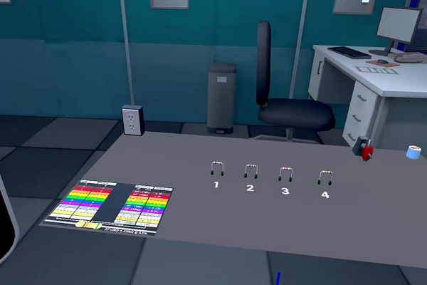
A resistor is the most numerous component in electronics: a mobile phone contains several hundred of them, and every one has to be the right value. The value is not printed as a number, because the parts are too small and too cheap for that. It is printed as a ring of coloured bands, a code introduced in the 1920s that is still used on through-hole resistors today, is readable from any angle, survives heat and solvents, and needs no magnifier. Being able to read it is the first practical skill of an electronics bench, and being able to check it with a meter is the second.
The quantity the bands encode is defined by Ohm’s law, R = V / I: a resistance of one ohm passes one ampere when one volt is placed across it. On a four-band resistor the first two bands give the two significant figures of that number, the third gives the power of ten to multiply them by, and the fourth states the tolerance — the manufacturer’s promise about how far the real part may stray from its nominal value. That fourth band is the interesting one, because it is an admission: resistors are made in bulk from a resistive film whose thickness cannot be controlled perfectly, so a part is sold not as a value but as a range.
In this laboratory you have four resistors with unknown values and a colour-code chart on the bench. You will decode each one from its bands, calculate the minimum and maximum resistance its tolerance allows, then measure it with an ohmmeter and decide whether the part meets its specification. The comparison between the two numbers — the one the manufacturer claims and the one the meter reports — is what the laboratory is really about, and it introduces the habit of asking not just what a value is but how well it is known.
Educational Goals
Reading the four-band colour code
- Decode any four-band resistor into a nominal value and a tolerance, including the gold and silver multipliers that give values below ten ohms.
- State which end of the resistor to read from, and explain how the tolerance band identifies it.
Tolerance and the range of acceptable values
- Calculate the minimum and maximum resistance permitted by a stated tolerance, and decide from a measurement whether a part is in specification.
- Express the difference between a measured and a nominal value as a percentage error, and compare it against the tolerance rather than against zero.
Using an ohmmeter
- Connect an ohmmeter to a component correctly, select an appropriate range, and read the display to the resolution it actually offers.
- Explain why a resistance measurement must be made on a component that is out of circuit and unpowered.
Recognising the limits of the instrument
- Estimate the resistance of the test leads and say for which of the four resistors it matters.
- Explain why very low resistances require a four-wire measurement, and why a two-wire reading of a fraction of an ohm cannot be trusted.
Preferred values and component selection
- Explain why resistors are manufactured in a geometric series of preferred values rather than in round numbers, and locate a given value in that series.
- Choose a tolerance appropriate to a task, and say what is gained and what it costs.
Protocol
- In this laboratory, you must identify the resistance of 4 resistors.
- To do this, you have the poster on your table at your disposal.
- A resistor is composed of 4 colored bands. Together, these 4 bands describe the resistance of the object.
- The first two bands form a number between 10 and 99.
- The third band gives the power of 10 applied to the first number.
- Finally, the fourth band indicates the tolerance. It’s the error in percentage of the given resistance.
Now try to identify the 4 resistors.
Anticipated Outcomes
The four resistors and their bands. The colours below are those rendered on the four resistors in the laboratory, so a teacher can check a student’s reading without loading the simulation.
| Resistor | Colour bands | Digits | Multiplier | Tolerance | Value |
|---|---|---|---|---|---|
| 1 | Brown – Green – Silver – Brown | 1, 5 | ×0.01 | ±1 % | 0.15 Ω |
| 2 | Brown – Grey – Brown – Brown | 1, 8 | ×10 | ±1 % | 180 Ω |
| 3 | Red – Red – Black – Brown | 2, 2 | ×1 | ±1 % | 22 Ω |
| 4 | Green – Orange – Gold – Brown | 5, 3 | ×0.1 | ±1 % | 5.3 Ω |
How to read the code. Each colour stands for a digit: black 0, brown 1, red 2, orange 3, yellow 4, green 5, blue 6, violet 7, grey 8, white 9. The first two bands are read straight off as a two-digit number. The third band is a multiplier — the same colour scale, but as a power of ten — with two extra colours used for fractions: gold means ×0.1 and silver ×0.01. The fourth band is the tolerance, and brown means the true value lies within 1 % of the nominal one.
Taking resistor 4 as a worked example: green and orange give the digits 5 and 3, so the two-digit number is 53; the gold third band multiplies by 0.1, giving 53 × 0.1 = 5.3 Ω; and the brown fourth band guarantees the true value lies between 5.25 and 5.35 Ω.
A note on the two smallest values. Resistors 1 and 4, at 0.15 Ω and 5.3 Ω, are at or below the resolution of an ordinary school multimeter, whose test leads alone contribute something like 0.2 Ω. Measuring them accurately calls for a four-wire technique or a dedicated milliohm meter. That limitation is explained on the poster in the laboratory, and it is worth drawing out with a senior class: the colour code tells you what the manufacturer intended, while measuring it tells you what your instrument can resolve, and the two are not the same question.
The four resistors on the bench have the values below. These four answers are the values of record for this laboratory; the band colours beside them are the only combination of four bands that produces each value, given two significant figures and a gold tolerance band, so they are reconstructed from the answers rather than read off the parts. Confirm them against the build before marking a student on the colours themselves.
| Resistor | Band 1 | Band 2 | Band 3 | Band 4 | Nominal (Ω) | Tolerance (%) | Minimum (Ω) | Maximum (Ω) |
|---|---|---|---|---|---|---|---|---|
| 1 | Brown | Green | Silver | Gold | 0.15 | ±5 | 0.1425 | 0.1575 |
| 2 | Brown | Grey | Brown | Gold | 180 | ±5 | 171 | 189 |
| 3 | Red | Red | Black | Gold | 22 | ±5 | 20.9 | 23.1 |
| 4 | Green | Orange | Gold | Gold | 5.3 | ±5 | 5.035 | 5.565 |
How the code works
Each colour carries a digit, a multiplier and, for the metallic colours, a tolerance. The multiplier column is simply ten raised to the digit, which is why gold and silver — the two colours with no digit — are the ones used for multipliers below one.
| Colour | Digit (bands 1 and 2) | Multiplier (band 3) | Tolerance (band 4) |
|---|---|---|---|
| Black | 0 | ×1 | — |
| Brown | 1 | ×10 | ±1 % |
| Red | 2 | ×102 | ±2 % |
| Orange | 3 | ×103 | — |
| Yellow | 4 | ×104 | — |
| Green | 5 | ×105 | ±0.5 % |
| Blue | 6 | ×106 | ±0.25 % |
| Violet | 7 | ×107 | ±0.1 % |
| Grey | 8 | ×108 | ±0.05 % |
| White | 9 | ×109 | — |
| Gold | — | ×0.1 | ±5 % |
| Silver | — | ×0.01 | ±10 % |
| No band | — | — | ±20 % |
Worked through for resistor 2, brown–grey–brown–gold: the first two bands give the digits 1 and 8, so the significant figures are 18; the third band, brown, multiplies by 101; and gold sets the tolerance at 5 %.
R = 18 × 101 = 180 Ω ± 5 %
The acceptance window follows from Rmin = R(1 − t) and Rmax = R(1 + t):
Rmin = 180 × (1 − 0.05) = 171 Ω Rmax = 180 × (1 + 0.05) = 189 Ω
A measurement is then judged against that window rather than against 180 Ω. The worked example in the results table at the foot of this page makes the point: a 470 Ω part measuring 455 Ω is off nominal by (455 − 470) / 470 = −3.2 %, which sounds like an error but is comfortably inside a ±5 % band, so the part is good. A resistor that measured exactly its nominal value would be the surprising outcome, not the expected one.
Why these values and not round numbers: preferred values
Resistors are not made in round numbers. They are made in geometric series called the E-series, chosen so that the tolerance bands of neighbouring values just meet and every possible resistance is covered without overlap. The E12 series steps by a factor of 101/12 = 1.21, that is 21 % per step, which is exactly what ±10 % parts need; the E24 series steps by 101/24 = 1.10, or 10 % per step, which is what ±5 % parts need. That is why the catalogue runs 10, 12, 15, 18, 22, 27, 33, 39, 47, 56, 68, 82 and then repeats one decade up, and why 15, 18 and 22 all appear among this laboratory’s resistors while 20, 50 and 100 do not.
Resistor 4 is the exception, and it is worth telling students so. The E24 series contains 51 and 56 but not 53, so a 5.3 Ω part at ±5 % is not a component that can be bought. Three significant figures of that kind belong to the E96 series, which is a ±1 % family and is marked with five bands, not four. Read resistor 4 as an arithmetic exercise in the gold multiplier rather than as a real part; 5.1 Ω or 5.6 Ω would be the buyable neighbours.
What the ohmmeter actually does, and where it stops working
An ohmmeter is not a fundamentally different instrument from a voltmeter. It passes a known small current through the component and measures the voltage this produces across it, then reports the quotient: R = V / I. Two consequences follow immediately. The component must be out of the circuit, because any parallel path carries part of the injected current and the meter reports the combination rather than the part; and the circuit must be unpowered, because an external voltage adds to the meter’s own and the reading becomes meaningless or the instrument is damaged.
The second consequence is that everything between the two probe tips is measured, including the test leads themselves. A pair of ordinary multimeter leads with alligator clips contributes something like 0.2 Ω, and that is a fixed addition, not a percentage:
| Resistor | Nominal (Ω) | Reading with 0.2 Ω of leads | Error (%) | Display resolution, 3½-digit meter | Verdict |
|---|---|---|---|---|---|
| 1 | 0.15 | 0.35 | +133 | 0.1 Ω (67 % of the value) | not measurable |
| 4 | 5.3 | 5.5 | +3.8 | 0.01 Ω | comparable to the tolerance |
| 3 | 22 | 22.2 | +0.9 | 0.1 Ω (0.45 %) | usable |
| 2 | 180 | 180.2 | +0.11 | 0.1 Ω (0.06 %) | good |
This is not a defect of technique but a limit of the two-wire method, and the professional answer to it is the four-wire or Kelvin connection: one pair of leads carries the current, a second pair senses the voltage at the body of the component, and the resistance of the current leads drops out of the calculation entirely. Milliohm meters and laboratory bench meters all work this way. Below about 1 Ω, a two-wire reading should be regarded as an upper bound rather than a measurement, and the honest procedure with an ordinary meter is to short the probes together, note the reading, and subtract it — which recovers resistor 4 but not resistor 1.
Resolution matters in the same direction. A 3½-digit meter offers 1999 counts, so on its 200 Ω range the smallest step it can show is 0.1 Ω. For the 180 Ω resistor that is 0.06 % — eighty times finer than the tolerance being checked, which is the comfortable case. For the 0.15 Ω resistor the same step is two thirds of the whole value, so even with perfect leads the meter can only say “0.1” or “0.2”. Choosing the lowest range that does not overflow is the single habit that most improves a resistance measurement.
One further real effect, small here but worth naming: resistance depends on temperature. A carbon-film resistor has a temperature coefficient of roughly 250 parts per million per degree, so warming the 180 Ω part by 20 °C changes it by 180 × 250 × 10−6 × 20 = 0.9 Ω, or 0.5 %. That is a tenth of the tolerance band and therefore invisible in this laboratory, but in a precision circuit built from ±1 % metal-film parts (50 ppm/°C) it is the dominant term, and it is the reason a specification sheet quotes a temperature as well as a value.
Summary of Assignment by Grade Range
Grade 9–10
Focus: reading the code and using the meter.
Activities: decode all four resistors from the chart, record the bands and the nominal value in a table, then measure each one with the ohmmeter and record the reading beside it. State which end of the resistor you read from and how you knew. Expected at this level: correct decoding of at least three of the four, correct use of the ohmmeter, and the observation in the student’s own words that a resistor has a range of acceptable values rather than one exact value.
Grade 11
Focus: quantitative treatment of tolerance and percentage error.
Activities: calculate the minimum and maximum permitted resistance for each part from R(1 ± t) with the substitution written out, then express each measurement as a percentage error from nominal and decide whether the part is in specification. Explain why a part that is 3 % off nominal passes while one that is 6 % off fails, even though both are close to the stated value. Locate each nominal value in the E12 or E24 series and identify the one that is not there. Expected at this level: correct arithmetic, a completed acceptance table, and a written statement of the difference between an error and a failure.
Grade 12 / College Level
Focus: measurement theory, instrument limits and specification.
Activities: derive the E-series from the requirement that consecutive tolerance bands meet, showing that a ±5 % family needs a step ratio of about 101/24, and use it to explain why 53 is absent. Measure the lead resistance by shorting the probes, then quantify its effect on each of the four parts and identify for which of them the two-wire method fails; describe the four-wire connection that removes it and explain why the current leads’ resistance drops out. Expected at this level: a written argument with assumptions stated and a recommendation of which resistors in this set are suitable for the exercise and which should be replaced.
Laboratory essentials
Instruments
- Ohmmeter (or a multimeter set to resistance)
- Connecting wires
- Alligator clips
- Resistor colour-code chart — the poster on the bench
Products
- Four four-band resistors of unknown value to the student: 0.15 Ω, 180 Ω, 22 Ω and 5.3 Ω, all with a gold (±5 %) tolerance band
Results table example
| Resistor | Band 1 | Band 2 | Band 3 | Band 4 | Nominal Value (Ω) | Tolerance (%) | Min (Ω) | Max (Ω) | Measured Value (Ω) |
| 1 | Yellow | Violet | Brown | Gold | 470 | 5 | 446.5 | 493.5 | 455 |
| 2 | |||||||||
| 3 | |||||||||
| 4 |