

Almost every electrical installation outside a string of fairy lights is wired in parallel. The lamps in a classroom, the outlets along a wall, the panels of a solar array and the cells of a battery pack are all connected across the same two supply rails, so that each one receives the full supply voltage and can be switched on or off without disturbing the others. The alternative — wiring devices one after another in a single loop, as in laboratory 075 — makes every device depend on all the others, which is why one failed bulb used to darken a whole string.
The physics of the arrangement rests on two statements. Because every branch is connected between the same pair of points, every branch carries the same voltage. And because charge cannot accumulate at a junction, the currents drawn by the branches must add up to the current delivered by the source; that is Kirchhoff’s first law. Its consequence is that resistances in parallel do not add — their reciprocals do — so a parallel combination always conducts better than any one of its branches, and adding a branch to a circuit increases the current the supply must provide.
In this laboratory you will build a two-branch circuit on a breadboard from a 12 V supply and three identical 5 Ω resistors: one branch holding two of them end to end, the second holding a switch and the third resistor. You will then use the multimeter twice over — first in voltage mode, connected across a component, and then in current mode, inserted into the circuit in place of the switch — measure the current in one branch and the current at the source, and use Kirchhoff’s first law together with Ohm’s law to work out the current in the branch you never metered and the resistance of a resistor you never removed.
Educational Goals
Building a circuit on a breadboard
- Turn a wiring instruction written as row-and-column coordinates into a working circuit, and recognise from the board’s internal connections which holes are already joined to each other.
- Add a second branch to an existing circuit without dismantling the first.
Telling a branch from a component
- State how many branches a circuit has, and decide for any two components whether they are in series with each other or in parallel.
- Explain why the two resistors of the first branch are in series even though the branch itself is in parallel with another.
Operating the multimeter
- Select the correct mode and the correct pair of jacks, and connect the instrument across a component to read a voltage but in line with it to read a current.
- Say what the instrument does to the circuit it is measuring in each of those two connections.
Applying Kirchhoff’s first law
- State that the currents arriving at a junction equal the currents leaving it, and use it to obtain a branch current that was never measured.
Applying Ohm’s law and the parallel rule
- Predict the equivalent resistance of two branches from the sum of their conductances, and check the answer against the measured source current.
- Recover an unknown resistance from one measured voltage and one deduced current.
Judging the measurement itself
- Explain why a voltmeter may be left across a live circuit while an ammeter may not, in terms of the meter’s own resistance.
- Estimate the error that real leads, real contacts and a real meter would add to each reading.
Recording and reporting
- Save the circuit diagram at each stage and report every measurement with its unit, so that another student could rebuild and re-measure the same circuit.
Protocol
Building the circuit
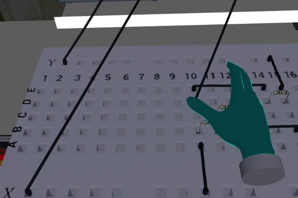
Connect the power supply to rows X and Y of the breadboard.
- Turn on the power supply using the switch and note the value displayed on the power supply.
- Take a wire and connect it from row X to location A-10.
- Take a resistor from the bin to your right and connect it from B-10 to B-11.
- Take a resistor from the bin on the right and connect it from C-11 to C-12.
- Take a wire and connect it from B-12 to B-15.
- Take a wire and connect it from E-15 to row Y.
You have built the first branch of your circuit. Since there is only one branch, the circuit is for now in series. A parallel circuit is made up of several branches.
- Take a switch and place it on your breadboard.
- Take a wire and connect it from E-10 to the switch.
- Take a wire and connect it from the switch to E-14.
- Take a resistor from the bin to your right and connect it from D-14 to D-15.
- Make sure that the switch is activated. If it is not, the circuit diagram will display only one branch
- Save the circuit.
Measuring a circuit
During the lab on series circuits, you unknowingly built a parallel circuit! And yes, you connected your multimeter in parallel with your resistor in order to find the voltage. But what would happen if you used the multimeter in series?
To know that, you must know how the multimeter works. Think of the multimeter as being a resistor. When it is set to V mode, its resistance is enormous! Using Kirchhoff’s laws and Ohm’s law, it is possible to prove that adding an enormous resistance in parallel does not affect the equivalent resistance of the previous circuit. However, each branch will have the same voltage!
However, if we put this large resistance in series, it will take all the voltage and thus block the rest of the circuit.
How do you measure the current? We use the A mode of the multimeter!
In this mode, we can imagine that the resistance is almost zero! Thus, the reverse reasoning of the one above applies. Try to convince yourself!
It is time to explore this new mode of the multimeter.
- Disconnect the connectors from the switch.
- Take one of the two free connectors and connect it to the central jack (COM) of the multimeter.
- Take the other connector and connect it to the left jack (10A) of the multimeter.
- Make sure that the central dial points to A.
- You have replaced the switch with the multimeter, thus putting the latter in series. The displayed value is the current in the branch.
- Save the diagram of your circuit.
- Try to measure the current at the source.
- Using the current of the branch and of the source, use Kirchhoff’s first law to find the current in the other branch.
- Try to measure the voltage in each resistor of the other branch. To do this, use the multimeter in V mode.
- With the current and the voltage of each resistor, we can invoke Ohm’s law and prove that they do indeed have the same resistance!
- Send the results
Anticipated Outcomes
Component values. The power supply is set to 12 V and all three resistors carry the bands Green – Black – Gold – Brown, that is 5 Ω ±1 % (laboratory 074 sets out the colour code). Where the protocol puts them decides everything that follows: steps 5 and 6 place two of them end to end inside the first branch, while step 13 adds the third as a branch of its own. Branch 1 therefore presents 10 Ω and branch 2 presents 5 Ω. The switch of steps 9 to 11 sits in branch 2, and it is that switch the multimeter replaces in step 15, so the current the meter reads is branch 2’s.
| Quantity | Expected value |
|---|---|
| Resistance of branch 1 (two 5 Ω resistors in series) | 10 Ω |
| Resistance of branch 2 (single 5 Ω resistor) | 5 Ω |
| Equivalent resistance of the two branches | 3.33 Ω |
| Voltage across each branch | 12 V |
| Current in branch 2, read in step 17 | 2.40 A |
| Current at the source, read in step 19 | 3.60 A |
| Current in branch 1, deduced in step 20 | 1.20 A |
| Voltage across each resistor of branch 1, step 21 | 6.0 V |
| Voltage across the resistor of branch 2 | 12 V |
Where the first three rows come from. In series, resistances add: R1 = 5 Ω + 5 Ω = 10 Ω. In parallel it is the conductances G = 1/R that add: Geq = 1/10 + 1/5 = 0.100 + 0.200 = 0.300 S, so Req = 1/0.300 = 3.33 Ω. For exactly two branches this is the same as the product over the sum, (10 × 5)/(10 + 5) = 50/15 = 3.33 Ω, but the reciprocal form is the one that generalises to three branches or more. Notice that the combination is smaller than either branch taken alone: offering the charge a second path can only make the whole easier to drive.
Where the currents come from. Each branch is connected directly across the supply, so Ohm’s law can be applied to each branch on its own: I1 = V/R1 = 12/10 = 1.20 A and I2 = V/R2 = 12/5 = 2.40 A. Their sum, 3.60 A, is what the source must deliver, and Ohm’s law applied to the equivalent resistance gives the same figure independently: 12/3.33 = 3.60 A. Those two routes agreeing is the check that the parallel rule was used correctly. The same result can be written as a current divider, Ik = I × Gk/Geq: I1 = 3.60 × 0.100/0.300 = 1.20 A and I2 = 3.60 × 0.200/0.300 = 2.40 A. The larger current goes down the smaller resistance — the exact opposite of the series case of laboratory 075, where the larger resistance took the larger share of the voltage.
What step 20 actually asks for. Only one branch current is ever metered, because the meter is sitting in branch 2. Kirchhoff’s first law at the junction where the branches meet supplies the other: I1 = Isource − I2 = 3.60 − 2.40 = 1.20 A. Steps 21 and 22 then close the argument without the branch ever being opened: measuring 6.0 V across one of branch 1’s resistors and dividing by the deduced current gives R = V/I = 6.0/1.20 = 5.0 Ω, which identifies it as the same part as the other two. Deducing a current you cannot reach and then using it to identify a component you cannot remove is the whole point of the laboratory.
Why 6 V and not 12 V. Every branch is connected straight across the supply, so every branch has the full 12 V across it. Within branch 1 that 12 V is then shared between two equal resistors, giving 6.0 V each; branch 2 contains a single resistor, which therefore takes the whole 12 V. Confusing a branch with the components inside it is the commonest error in this laboratory, and the rule worth memorising is symmetrical: parallel branches share a common voltage and divide the current, while components in series inside a branch share a common current and divide the voltage.
What the multimeter does to the circuit. The protocol asks you to reason about the instrument as though it were a resistor, and the reasoning becomes concrete once numbers are attached to it. A digital multimeter presents roughly 10 MΩ between its terminals in voltage mode and roughly 0.01 Ω — a shunt — on a 10 A current range. Those two values, four orders of magnitude above and three below the 5 Ω under test, are what make one connection harmless and the other destructive.
| Mode and connection | Resistance the meter adds | Effect on the circuit | What is read |
|---|---|---|---|
| V mode, across a component | 10 MΩ in parallel | 5 Ω becomes 4.999 997 5 Ω, a change of 5 × 10⁻⁵ % | the true voltage |
| V mode, inserted in line | 10 MΩ in series | branch current falls to 12/(107 + 5) = 1.2 µA and its resistor drops 6 µV: the branch is off | almost the whole 12 V, standing across the meter |
| A mode, inserted in line | ≈ 0.01 Ω in series | branch resistance becomes 5.01 Ω and the current reads 0.2 % low | the branch current |
| A mode, across a component | ≈ 0.01 Ω in parallel | a near short circuit straight across the supply | nothing useful — this is the connection that blows the meter’s fuse |
What the simulation does not charge you for. Five ohms is a very small resistance to put across 12 V, and the power that follows is large. Each resistor of branch 1 dissipates I2R = 1.202 × 5 = 7.2 W; the resistor of branch 2 dissipates 2.402 × 5 = 28.8 W; and the supply delivers 12 × 3.60 = 43.2 W altogether. A quarter-watt carbon-film resistor of the kind pictured would be overloaded twenty-nine times over in branch 1 and a hundred and fifteen times over in branch 2, and 3.60 A is well past the roughly 1 A that a breadboard’s spring contacts are rated to carry. Built on a bench, this circuit would burn. Multiplying every resistance by two hundred — three 1.0 kΩ parts — leaves every voltage on the page and every ratio in the argument untouched while bringing the currents to 6.0, 12.0 and 18.0 mA and the worst dissipation to 0.14 W. The same objection and the same remedy were recorded for laboratory 075.
What a real bench would read. Jumper wires, breadboard contacts and meter leads together contribute something of the order of 0.5 Ω (laboratory 074 puts a pair of clip leads alone at about 0.2 Ω). Against branch 2’s 5 Ω that is a tenth, so a real measurement would return nearer 12/5.5 = 2.18 A than 2.40 A, and a source current nearer 3.3 A than 3.60 A. Two consequences follow for marking. The values in the table above are ideal ones, produced by a simulation in which wires have no resistance; and the ±1 % tolerance printed on the resistors cannot be tested at these resistances at all, because the wiring is ten times less certain than the parts it connects. A student who measured 2.2 A on real hardware has not made a mistake.
Summary of Assignment by Grade Range
Grade 9–10
Focus. What a parallel circuit is, and how to build one that works.
Activities. Assemble the first branch, check that it conducts, then add the switch and the second branch. Use the multimeter in V mode only, confirming that both branches have 12 V across them and that each resistor of branch 1 has 6.0 V. Open and close the switch and observe that branch 1 is unaffected.
Expected of the student. Name the two arrangements and say which is which from a diagram; state that parallel branches all have the same voltage; connect a voltmeter across a component without help; describe in words why one lamp failing in a house does not switch off the others.
Grade 11
Focus. Quantitative treatment of the whole circuit.
Activities. Predict all the currents from Ohm’s law before touching the meter, then measure the branch current and the source current and compare. Obtain the unmeasured branch current from Kirchhoff’s first law, compute the equivalent resistance both from the reciprocal sum and from the source current, and recover the resistance of a branch 1 resistor from V and I.
Expected of the student. Apply 1/Req = 1/R1 + 1/R2 with the substitution written out; explain why the equivalent resistance is smaller than either branch; use the current divider to say which branch carries more and why; present the measurements in a table with units.
Grade 12 / College Level
Focus. The measurement itself as an object of study, and the limits of the apparatus.
Activities. Derive the current divider from Kirchhoff’s first law and Ohm’s law rather than quoting it. Quantify the meter’s loading in all four connections of the table above. Propagate the ±1 % tolerances through to the equivalent resistance, estimate the wiring resistance and the discrepancy it would cause on real hardware, and calculate the power rating each resistor in this circuit would actually need.
Expected of the student. Justify from the meter’s internal resistance why a voltmeter goes across and an ammeter in line, and predict what happens in each of the two wrong connections; separate an instrument error from a component tolerance; recognise that a circuit can be electrically correct and still not be physically realisable as specified, and propose a scaling that fixes it while preserving the physics.
Laboratory essentials
Instruments
- Power supply (12 V DC)
- Breadboard
- Multimeter (V and A modes; COM and 10 A jacks)
- Connecting wires
- Resistors (3 × 5 Ω ±1 %, banded Green – Black – Gold – Brown)
- Switch (one, placed in the second branch)