

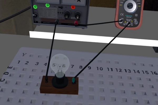
A filament lamp is the simplest instrument in a laboratory that turns an electrical quantity into something the eye can read directly. Dimmer switches, the fading headlights of a car whose battery is going flat, and the brightness control on an instrument panel all work on the same principle: change the current through the filament and its temperature, and therefore its light, changes with it. The relationship is worth pinning down because it is not the one most people expect — light does not fall off in step with current, it falls off very much faster.
The reason is that the filament is heated by the power delivered to it, and power is not proportional to current but to its square, P = I2R. In a series circuit there is only one path, so the same current passes through every component; adding a resistor raises the total resistance, and by Ohm’s law I = V/R the current everywhere falls. The lamp then receives a smaller current and, at the same time, a smaller share of the supply voltage, and the two effects multiply. A further step of the same kind links power to what is actually seen, because a cooler filament radiates less and radiates a smaller fraction of what it does emit as visible light.
In this laboratory you will build a series circuit containing nothing but a 12 V supply and a lamp, measure the current with a multimeter and record how bright the lamp appears. You will then add a 5 Ω resistor and repeat the measurement, add a second one and repeat it again, and use the three pairs of readings to decide what kind of relationship connects current to brightness: constant, linear, or something steeper.
Educational Goals
Assembling and modifying a series circuit
- Build a working single-loop circuit from a supply, a lamp and connecting wires, then extend it without dismantling what is already there.
- Recognise that in a series circuit the current is the same at every point, so it does not matter where the meter is inserted.
Measuring current
- Put a multimeter into current mode, insert it in line with the circuit rather than across a component, and read the current to the precision the instrument offers.
- Record each reading with its unit alongside the circuit that produced it, so the three trials can be compared afterwards.
Applying Ohm’s law
- Predict the current in each of the three circuits from the total resistance before measuring it, and compare prediction with measurement.
- Explain why adding a resistor in series reduces the current through a component that was not touched.
Relating power to brightness
- Compute the power dissipated in the lamp from P = I2R and show that it falls as the square of the current.
- Explain why the lamp both carries less current and takes a smaller share of the supply voltage as resistors are added.
Identifying a relationship from data
- Decide from three measurements whether a relationship is constant, linear or steeper than linear, and say what further measurements would settle it.
- Plot current against the reciprocal of the total resistance and recognise a straight line through the origin as a confirmation of Ohm’s law.
Judging the limits of a qualitative observation
- Give reasons why an eye is a poor photometer, and propose how the brightness comparison could be made quantitative.
- State at least one way in which a real filament departs from the constant resistance assumed in the calculation.
Protocol
The goal of this laboratory is to observe the impact of current on the intensity of a lamp.
Setup
First, build a series circuit consisting only of a lamp or an LED.
- Turn on the power supply.
- Use the multimeter to measure the circuit current.
- Write down the current and a qualitative measure of the light intensity.
- Save the circuit.
- Add a resistor to the circuit and repeat the previous steps.
- Add another resistor to the circuit and repeat the previous steps.
We now have three intensity values as a function of current. What relationship is observed? Is it constant, linear, exponential…
Anticipated Outcomes
Component values. The power supply is set to 12 V. The lamp presents 5 Ω at its working temperature, and each resistor added to the circuit carries the bands Green – Black – Gold – Brown, that is 5 Ω ±1 % (laboratory 074 sets out the colour code). The circuit is a single loop throughout, so the same current passes through the lamp, the resistors and the meter alike, and the meter may be inserted anywhere in the loop with the same result.
| Step | Circuit | Total resistance | Current | Power in the lamp | Brightness |
|---|---|---|---|---|---|
| 2 | lamp alone | 5 Ω | 2.40 A | 28.8 W | brightest |
| 5 | lamp + 1 resistor | 10 Ω | 1.20 A | 7.2 W | clearly dimmer |
| 6 | lamp + 2 resistors | 15 Ω | 0.80 A | 3.2 W | dimmest |
Working the three rows. Resistances in series add, so the totals are 5, 5 + 5 = 10 and 5 + 5 + 5 = 15 Ω. Ohm’s law then gives the current in each case: I = 12/5 = 2.40 A, I = 12/10 = 1.20 A and I = 12/15 = 0.80 A. The power reaching the filament is P = I2Rlamp = 2.402 × 5 = 28.8 W, then 1.202 × 5 = 7.2 W, then 0.802 × 5 = 3.2 W. The same three numbers come out of P = Vlamp × I once the voltage across the lamp is worked out from Vlamp = I × 5 Ω, which is 12 V, then 6.0 V, then 4.0 V: 12 × 2.40 = 28.8 W, 6.0 × 1.20 = 7.2 W and 4.0 × 0.80 = 3.2 W. Two independent routes to the same answer is the check that the circuit has been understood; the 4.0 V of the third trial is the same figure laboratory 075 measures on its 5 Ω resistor, because that is the same circuit.
Why the light falls faster than the current. Two things happen at once when a resistor is added. The current falls, and the share of the supply voltage that lands on the lamp falls with it — from all 12 V, to a half, to a third. Power is the product of the two, so it falls as the square: the three figures stand in the ratio 9 : 2.25 : 1. Halving the current from 2.40 A to 1.20 A leaves the lamp with a quarter of its power, not half. Expressed as a fraction of what the supply delivers (28.8 W, 14.4 W and 9.6 W in the three trials), the lamp receives 100 %, 50 % and 33 % — the rest is heating the resistors. This is the answer to the question the protocol poses: the relationship is neither constant nor linear but a power law, brightness ∝ I2 at fixed lamp resistance, and equivalently ∝ 1/Rtotal2.
And the eye sees something steeper still. The power figures are what the filament receives, not what leaves it as visible light. A tungsten filament radiates as its temperature to the fourth power, and the fraction of that radiation falling inside the visible band climbs steeply with temperature as well, because Wien’s law puts the peak of a 2800 K filament at about 1.0 µm, well into the infrared. The standard empirical scaling for a tungsten lamp near its rated voltage, luminous flux ∝ V3.4, therefore predicts that the second trial at half the lamp voltage emits about 0.53.4 = 9.5 % of the light of the first, and the third at a third of the voltage about 2.6 % — far below the 25 % and 11 % that the power ratios alone suggest. Pushed this far below rated voltage the scaling is only indicative, and in a physical laboratory the third trial would most likely be a dull orange glow rather than a dim white one. The colour shift is itself worth pointing out to students: a dimmed filament lamp does not just emit less light, it emits redder light, which is why filament dimmers and daylight-balanced photography do not mix.
| Trial | Current, relative | Power in the lamp, relative | Light emitted, relative | Brightness as judged by eye, relative |
|---|---|---|---|---|
| 2 — lamp alone | 1.00 | 1.00 | 1.00 | 1.00 |
| 5 — one resistor added | 0.50 | 0.25 | ≈ 0.10 | ≈ 0.46 |
| 6 — two resistors added | 0.33 | 0.11 | ≈ 0.03 | ≈ 0.30 |
The lamp’s resistance is not really constant. The 5 Ω used throughout is the filament’s resistance when hot. Tungsten’s resistivity rises steeply with temperature — a coefficient of about 0.0045 per kelvin gives a factor of ten to fifteen between room temperature and 2800 K — so the same filament measured cold would read a few tenths of an ohm, and the lamp draws a large inrush current at the instant it is switched on. It also means the calculation above is self-referential: as resistors are added the filament cools, its resistance falls below 5 Ω, the total resistance is therefore a little less than 10 or 15 Ω, and the real current is a little higher than the table says while the lamp’s share of the voltage is a little lower. The simulation models a fixed 5 Ω, which keeps the arithmetic clean and is the right simplification for this level, but a class that measures the voltage across the lamp as well as the current can see the effect directly: V/I would come out below 5 Ω in the dimmer trials. That single extra reading is the most valuable addition a teacher can make to this protocol.
A warning about the LED option. The protocol offers “a lamp or an LED”, and the two do not behave alike. An LED is not a resistor: it holds a roughly fixed forward voltage of about 2 V and its current is set by whatever else is in the circuit, so it must always be operated with a current-limiting resistor. Connected alone across 12 V through this circuit’s wiring it would pass an enormous current — even with both 5 Ω resistors in place, (12 − 2)/10 = 1 A against a typical 20 mA rating — and fail immediately. On a bench, an LED here needs about 500 Ω, not 5. The physics of the answer changes too: an LED’s light output is close to proportional to its current, not to the square of it, so the relationship the laboratory sets out to identify is a different one depending on which component is chosen. The values on this page are for the lamp.
What the simulation does not charge you for. These currents are large for the components pictured. The lamp dissipates 28.8 W in the first trial, which is a vehicle lamp rather than an indicator bulb; each 5 Ω resistor dissipates I2R = 7.2 W in the second trial and 3.2 W in the third, twenty-nine and thirteen times a quarter-watt carbon-film part; and 2.40 A is well beyond the roughly 1 A a breadboard’s spring contacts are rated to carry. Built on real hardware as specified, this circuit would overheat. Multiplying every resistance by two hundred keeps all three current ratios, all three voltage divisions and the entire argument intact at safe power levels. The same objection was recorded for laboratories 075 and 076.
Honest limits of this experiment. Three points are not many from which to name a relationship, and they are not evenly spaced: the currents 2.40, 1.20 and 0.80 A follow 12/(5n) for n = 1, 2, 3, which is a hyperbola in the number of resistors, so a student who plots brightness against that number sees a curve produced by the circuit rather than by the lamp. The clean test is to plot current against 1/Rtotal, which must be a straight line through the origin of slope 12 V. Brightness itself is only ever recorded in words, so the last two columns of the second table cannot be checked against anything the protocol measures; a light meter, or a photograph taken at fixed exposure, would turn the laboratory’s central claim into a measurement. And the eye adapts between observations, so the three lamps should be compared in the same room, in the same ambient light, and ideally within a few seconds of each other.
Results are found at this link
Summary of Assignment by Grade Range
Grade 9–10
Focus. Building a series circuit and observing what adding resistance does to it.
Activities. Assemble the lamp circuit, measure the current, describe the brightness in words, then add one resistor and repeat, and a second and repeat. Record the three currents in a table alongside the three descriptions.
Expected of the student. State that the current is the same everywhere in a series loop; say that adding resistance reduces the current; connect a multimeter in line with the circuit rather than across a component; and notice that the light falls off more sharply than the current does, even without being able to say by how much.
Grade 11
Focus. Quantitative treatment of current, voltage and power.
Activities. Predict the three currents from I = V/Rtotal before measuring them; compute the voltage across the lamp and the power it dissipates in each trial by both routes, P = I2R and P = VI; and plot current against 1/Rtotal to test Ohm’s law directly.
Expected of the student. Show that the power ratios are 9 : 2.25 : 1 and explain the squaring; state that the lamp receives 100 %, 50 % and 33 % of the supply’s power in the three trials and say where the rest goes; identify the relationship as a power law rather than a linear one and justify the choice from the data.
Grade 12 / College Level
Focus. The chain from electrical power to perceived light, and the assumptions hidden in it.
Activities. Follow the argument through its three stages — power to filament temperature, temperature to radiated and visible flux, flux to perceived brightness — and estimate the relative light output of the three trials. Examine the constant-resistance assumption using tungsten’s temperature coefficient, and design the extra measurement that would expose it. Compute the power rating each component in this circuit would need on real hardware, and propose a scaling that makes the circuit buildable.
Expected of the student. Explain why a dimmed filament lamp shifts red, using Wien’s displacement law; distinguish radiated power from luminous flux from perceived brightness and say which of the three the experiment actually observes; argue why an LED substituted for the lamp would give a different relationship and would not survive the circuit as specified; and state what a three-point data set can and cannot establish.
Laboratory essentials
Instruments
- Power supply (12 V DC)
- Breadboard
- Multimeter (A mode; COM and 10 A jacks)
- Connecting wires
- Lamp (5 Ω at its working temperature)
- Resistors (2 × 5 Ω ±1 %, banded Green – Black – Gold – Brown)
- LED (named in the protocol as an alternative to the lamp — see the caution in Anticipated Outcomes before using one)
- Resistor colour code chart