

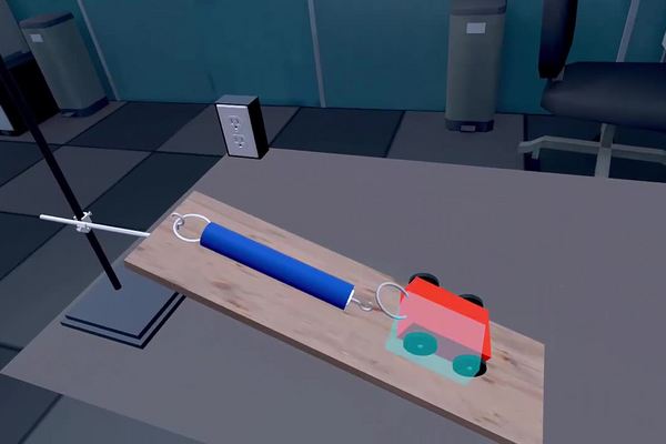
An inclined plane is the oldest of the simple machines and still one of the most useful: it is why a wheelchair ramp exists, why a mountain road switches back instead of climbing straight up, and why a loading dock has a slope rather than a step. In every case the ramp does not reduce the work required to raise a load — it reduces the force required, by spreading that work over a longer path. Knowing how much force a given slope demands is what allows a ramp to be designed, a winch to be sized or a hillside road to be given a safe gradient.
The physics is a decomposition of a single vector. Gravity pulls the cart straight down with its full weight Fg = m g, but the board can only be left along its surface or pressed into perpendicular to it. Resolving the weight along those two directions gives a component parallel to the slope, Feff = Fg sin θ, which is the part that tends to make the cart run down, and a component perpendicular to it, N = Fg cos θ, which the board simply supports. Only the parallel component — the effective force — has to be held back, and because sin θ grows from zero at the horizontal to one at the vertical, the same cart demands a different restraint on every slope.
In this laboratory you will measure that component directly. A cart of known mass is attached to a dynamometer aligned with a board, and the board is set at roughly 20°, 40° and 60° by moving a clamp up a universal support. At each angle you will read the force the dynamometer holds, calculate what Fg sin θ predicts, and compare the two. The comparison is the point of the experiment: agreement confirms the decomposition, and the size of any disagreement tells you how well the measurement was made.
Educational Goals
Familiarization with the laboratory environment
- Identify the parts of an inclined-plane set-up: the universal support, the clamp that fixes the height, the board, the protractor and the dynamometer with its hook.
- Set and read an angle of inclination with a protractor, and record it as a measured quantity rather than as a nominal setting.
Correct use of a dynamometer
- Attach the dynamometer so that it lies parallel to the board, and explain why a misaligned dynamometer reads low.
- Read a force in newtons to the resolution the instrument actually offers, and check its zero before loading it.
Resolving a force into components
- Draw the free-body diagram of a cart at rest on a slope, showing the weight, the normal force and the force in the dynamometer.
- Resolve the weight into a component along the slope and a component perpendicular to it, and write each as a product of Fg and a trigonometric function of the angle.
Predicting and testing a quantitative relationship
- Calculate the weight of the cart from Fg = m g and the theoretical effective force from Feff = Fg sin θ.
- Predict the effective force at an angle not tested, and describe how the prediction could be checked.
- Explain why the effective force does not increase in equal steps for equal increases in angle.
Comparing measurement with theory
- Tabulate measured and calculated values side by side and express the difference both absolutely and as a percentage.
- Decide whether an observed difference is large enough to require a physical explanation, or small enough to be attributed to the precision of the instruments.
Connecting force to the idea of a machine
- Explain why a ramp reduces the force needed to raise a load without reducing the work done.
- Calculate the mechanical advantage of a slope from its angle and relate it to the distance travelled along the board.
Protocol
- Position the clamp on the universal support at a height of approximately 20 cm (lowest position).
- Then place the board on the clamp so that it rests at an angle of approximately 20° relative to the horizontal (use a protractor).
- The value of the angle is noted in the results table.
- Place the dynamometer on the board by attaching it to the hook.
- Place the cart on the board, attach it to the hook of the dynamometer. Ensure that the dynamometer remains parallel to the board.
- The effective experimental force measured by the dynamometer is found in the results table.
- Repeat step 1 by fixing the clamp to the universal support at a position just slightly higher to tilt the board at an angle of approximately 40° relative to the horizontal.
-> The cart will then move downward. The effective experimental force measured by the dynamometer is found in the results table.
- Finally, repeat step 1 by attaching the clamp to the universal support at the highest position to tilt the board at an angle of approximately 60° relative to the horizontal.
-> The cart will then move downward. The effective experimental force measured by the dynamometer is found in the results table.
Anticipated Outcomes
The weight of the cart. Everything on this page follows from one number. The cart has a mass of 250 g, so its weight is Fg = m g = 0.250 kg × 9.8 N/kg = 2.45 N. That weight is the same at every angle; only the fraction of it that acts along the board changes.
The decomposition. The weight acts vertically downward. Taking axes along the board and perpendicular to it, it resolves into
Feff = Fg sin θ (along the slope, tending to move the cart down)
N = Fg cos θ (perpendicular to the slope, carried by the board)
With the cart at rest and the dynamometer parallel to the board, the dynamometer must supply exactly the first of these, so its reading is the effective force. Substituting at 20°: Feff = 2.45 × sin 20° = 2.45 × 0.342 = 0.84 N.
| Angle θ | sin θ | Theoretical Feff = Fg sin θ | Experimental Feff | Difference | Normal force N = Fg cos θ |
|---|---|---|---|---|---|
| 20° | 0.342 | 0.84 N | 0.82 N | −0.02 N (2.1 %) | 2.30 N |
| 40° | 0.643 | 1.57 N | 1.55 N | −0.02 N (1.6 %) | 1.88 N |
| 60° | 0.866 | 2.12 N | 2.10 N | −0.02 N (1.0 %) | 1.23 N |
A check that costs nothing. The two components are perpendicular, so they must recombine to the full weight: Feff2 + N2 = Fg2. At 20°, 0.842 + 2.302 = 0.71 + 5.29 = 6.00, and √6.00 = 2.45 N. The same holds at every angle, and it is the quickest way for a student to catch a sine used where a cosine was meant — a swapped pair fails this test immediately.
Why the force does not rise in equal steps. The angle increases by 20° twice, but the force does not: it rises by 0.73 N from 20° to 40° and by only 0.55 N from 40° to 60°. The reason is that the effective force follows the sine of the angle, not the angle itself, and the sine flattens as it approaches 1. Near the horizontal the relationship is almost linear, since sin θ ≈ θ for small angles measured in radians, so doubling a shallow slope very nearly doubles the force needed; near the vertical, additional tilt buys almost nothing, because the weight is already acting almost entirely along the board. The endpoints make the shape obvious: at 0° the effective force is zero and the board carries the whole weight, while at 90° the effective force is the whole 2.45 N and the board carries nothing — the cart is simply hanging from the dynamometer.
The ramp as a machine. To raise the cart through a height h the dynamometer must pull it a distance h / sin θ along the board, exerting Fg sin θ the whole way. The work done is therefore Fg sin θ × h / sin θ = Fg h, independent of the angle: the slope changes the force and the distance in exactly compensating proportion, and buys no energy at all. The ideal mechanical advantage is 1 / sin θ, which is 2.92 at 20°, 1.56 at 40° and 1.15 at 60°. This is why a shallow ramp is easy and long, and why the shallowest board in this experiment is the one that demands the least force.
Summary of Assignment by Grade Range
Grade 9–10
Focus: the observation that a steeper slope demands a larger force, and the vocabulary needed to describe it.
- Set the board to each of the three angles using the protractor, and record the angle actually obtained rather than the angle intended.
- Attach the cart to the dynamometer with the dynamometer parallel to the board, and record the force at each angle in a table.
- State in words what happens to the force as the board is raised, and give two everyday examples of a ramp chosen to make a load easier to move.
- Calculate the weight of the cart from Fg = m g and check that no measured force exceeds it, explaining why none can.
Grade 11
Focus: resolving the weight into components and testing the prediction quantitatively.
- Draw a labelled free-body diagram of the cart on the slope, showing the weight, the normal force and the dynamometer force.
- Calculate the theoretical effective force Feff = Fg sin θ at all three angles, showing one full substitution.
- Calculate the normal force N = Fg cos θ at each angle and verify that Feff2 + N2 = Fg2.
- Tabulate the percentage difference between measurement and theory at each angle and comment on whether it grows or shrinks with the slope.
- Predict the effective force at 30° and at 75°, and explain why the increase from 20° to 40° is larger than the increase from 40° to 60°.
- Explain why a ramp reduces the force required but not the work done, using the distance travelled along the board.
Grade 12 / College Level
Focus: hypothesis testing with the resolved-weight model.
- Derive Feff = Fg sin θ from the free-body diagram by resolving along the axes of the incline, stating the equilibrium condition used.
- Discuss the difference between rolling resistance and sliding friction, and explain which applies to a wheeled cart and why the two scale differently with load.
Laboratory essentials
Instruments
- Universal support (stand)
- Clamp
- Wooden board (inclined plane)
- Cart (250 g)
- Dynamometer
- Angle protractor
Products
- None — this laboratory uses no chemical reagents.