

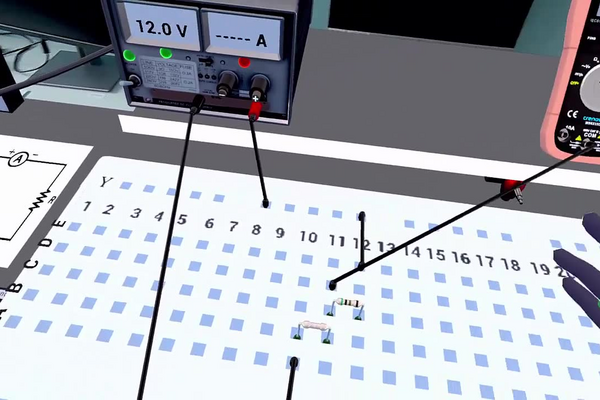
Every piece of electronics ever built starts as a loop: a source, a conductor and something that limits the current. A breadboard is the standard way to make that loop temporarily, without soldering, so that a design can be tried, measured and changed in minutes. It is the tool every electronics laboratory, prototyping bench and undergraduate course begins with, and the reason a modern product can go from a sketch to a working circuit in an afternoon.
Two rules govern everything measured on such a loop. Ohm’s law, V = IR, relates the current through a component to the voltage across it. Kirchhoff’s loop rule states that the voltages around any closed loop must sum to zero — energy given to each charge by the supply is entirely given back to the components it passes through. Together they have a useful consequence: in a single loop the current is the same everywhere, so components in series divide the supply voltage between them in proportion to their resistances. That is enough to find the value of a component you cannot read, using nothing but a voltmeter and one resistor whose value you do know.
In this laboratory you will wire a power supply to a breadboard, build a series circuit containing a known resistor and a mystery resistor whose markings have been removed, save a diagram of what you built, and then measure a single voltage with a multimeter. From that one reading, the supply voltage and the known resistance, you will calculate the current in the circuit, the voltage across the mystery resistor, and finally its resistance — a first exercise in getting a quantity you cannot measure directly out of quantities you can.
Educational Goals
Understanding the components and the breadboard
- State what a breadboard, a bench power supply, a resistor and a multimeter each do in a circuit.
- Read the breadboard’s internal connections from the poster and predict which holes are electrically the same point.
Building a series circuit
- Wire a supply to the breadboard rails and place two components in series between them, checking the loop is complete before switching on.
- Redraw the assembled circuit as a schematic and recognise that many different physical layouts give the same schematic.
Measuring with a multimeter
- Connect a multimeter as a voltmeter — in parallel with the component of interest, dial on V — and read it to the resolution the display offers.
- Explain why a voltmeter must have a very high resistance, and why an ammeter must have a very low one.
Applying Ohm’s law and Kirchhoff’s loop rule
- Calculate the current in a series circuit from the voltage across a known resistor, then use the loop rule to find the voltage across an unknown one.
- Determine an unknown resistance two independent ways — from its own voltage and current, and by subtracting the known resistance from the circuit total — and check that they agree.
Judging the quality of a result
- Estimate the power dissipated in each component and check it against what the components can survive.
Recording work
- Save the circuit diagram and the photograph of the assembled circuit, so that a result can be traced back to the arrangement that produced it.
Protocol
In front of you there is a breadboard, a power supply and a multimeter.
- The breadboard is the large white panel in front of you. It is a tool that makes it possible to build a circuit easily. Everything that is in a numbered column is connected to everything else within that column. The same thing is true for rows X and Y.
- The power supply is the gray box on the shelf. It is like an electrical outlet! It provides the energy needed for our circuits.
- The multimeter is the rectangle with orange outlines. It is a tool that makes it possible to study the current as well as the voltage of your circuit.
To your right are bins containing various electronic components. In this experiment, you will only have access to wires and resistors.
Building the circuit
- Take two wires from the bin and place them in front of you.
- Take the end of one of the wires and connect it to the black terminal of the power supply.
- Take the other end of the same wire and connect it on row X of the breadboard.
- Take one end of the other wire and connect it to the red terminal of the power supply.
- Take the other end of this same wire and connect it on row Y of the breadboard .
The power supply is now connected to the breadboard. It is now possible to use rows A to E to do the experiment.
- Turn on the power supply using the switch and note the value displayed on the power supply.
- Take a wire and connect it from row X to location A-10.
- Take the mystery resistor on the shelf in front of you and connect it from B-10 to B-11
- Take a resistor from the bin to your right and connect it from C-11 to C-12
- Using the color guide, note the resistance of the resistor.
- Take a wire and connect it from E-12 to row Y.
You have built your first circuit! This circuit could have been built in many other ways. Here, the exact configuration was provided but the important thing is only to respect the connections of the breadboard as illustrated on the poster on the table.
Saving a circuit
- At the bottom right of the main menu of this tablet, you can find a button that makes it possible to view the circuit. Once in this interface, you can see a diagram representing the circuit you have just created. In this interface, two buttons are accessible. One to save the image in the results, another to change the display type to a camera.
- Save the diagram and the camera view of the circuit.
Measuring a circuit
Now that the circuit is built, it must be studied! To do this you must use the multimeter.
- Take a wire and connect it to the central jack (COM) of the multimeter.
- Take another wire and connect it to the right jack (VHz) of the multimeter.
- Make sure that the central dial points to V.
- You are now ready to measure the voltage of your resistor, to do this, take the two remaining ends of the wires and connect them to locations D-11 and D-12.
Saving the circuit diagram
- Turn off the power supply
- Using the resistance and the voltage noted, use Ohm’s law to calculate the current in the known resistor and therefore in the circuit.
- With the measured voltage and the voltage provided by the power supply, use Kirchhoff’s second law to calculate the voltage of the mystery resistor.
You now know the voltage and the current of the mystery resistor. Use Ohm’s law to discover its resistance.
- Send the results
Anticipated Outcomes
Component values. The power supply delivers 12 V. The resistor taken from the bin is banded green – black – gold – brown, which decodes as the digits 5 and 0 with a gold multiplier of ×0.1, so 5 Ω ±1 % (the same gold multiplier that laboratory 074 introduces). The second resistor has its bands scratched off; its value is 10 Ω, and the whole point of the exercise is to arrive at that number from measurements rather than from the code.
| Quantity | Expected value | Where it comes from |
|---|---|---|
| Supply voltage | 12 V | read from the power supply display |
| Total resistance of the series circuit | 15 Ω | 5 + 10, in series |
| Current through the circuit | 0.80 A | 12 V / 15 Ω |
| Voltage across the 5 Ω resistor (step 17) | 4.0 V | 0.80 A × 5 Ω, the measured quantity |
| Voltage across the unmarked resistor | 8.0 V | 12 V − 4.0 V, by the loop rule |
| Sum of the two voltage drops | 12 V | equal to the supply, as it must be |
| Resistance of the unmarked resistor | 10 Ω | 8.0 V / 0.80 A |
Why the numbers come out this way
The two resistors sit in one loop, so every electron that passes through the first passes through the second: the current is the same at every point in a series circuit. This is Kirchhoff’s current rule in its simplest form — there is nowhere else for charge to go. The resistances therefore add:
Rtotal = R1 + R2 = 5 + 10 = 15 Ω
and Ohm’s law applied to the whole loop gives the current:
I = V / Rtotal = 12 V / 15 Ω = 0.80 A
Because the current is common to both, the same law applied to each component separately shows that the supply voltage is divided in proportion to the resistances:
V1 = I R1 = 0.80 × 5 = 4.0 V and V2 = I R2 = 0.80 × 10 = 8.0 V
The resistor with twice the resistance takes twice the voltage. Kirchhoff’s loop rule is then the check that the accounting closes:
Vsupply − V1 − V2 = 12 − 4.0 − 8.0 = 0
Identifying the unmarked resistor two ways
The route the protocol asks for runs through the mystery resistor’s own quantities. Its voltage is what the loop rule leaves over, 12 − 4.0 = 8.0 V, and its current is the circuit current found from the known resistor, 4.0 V / 5 Ω = 0.80 A. Ohm’s law rearranged then gives the answer:
R2 = V2 / I = 8.0 V / 0.80 A = 10 Ω
A second, independent route gives the same number and is worth asking students for, because agreement between two derivations is how a result is trusted: the total resistance of the loop is Rtotal = 12 V / 0.80 A = 15 Ω, and subtracting the resistor whose value is known leaves 15 − 5 = 10 Ω. The two agree exactly, which they must, since both rest on the same single measurement.
The point most often missed: the 5 Ω resistor is the ammeter. The multimeter’s dial is set to V and stays there, so the current is never measured at any stage of this laboratory — it is inferred, by using a resistor of known value as a current sensor. That is exactly how current is measured inside almost every instrument and power supply ever built: a small precise resistance, called a shunt, is placed in the path and the voltage across it is read. It also explains where the precision of the final answer comes from, and why the tolerance printed on that one resistor matters more than anything else on the bench.
The power in this circuit is the one thing to check before building it
Resistances of a few ohms across a 12 V supply draw a great deal of current, and the energy has to go somewhere. From P = VI, or equivalently P = I2R:
| Component | Voltage (V) | Current (A) | Power dissipated (W) | Against a standard rating |
|---|---|---|---|---|
| 5 Ω known resistor | 4.0 | 0.80 | 3.2 | 13× a quarter-watt part |
| 10 Ω unmarked resistor | 8.0 | 0.80 | 6.4 | 26× a quarter-watt part |
| Whole circuit | 12 | 0.80 | 9.6 | — |
A general-purpose through-hole resistor is rated at a quarter of a watt. The two parts in this circuit are being asked to dissipate thirteen and twenty-six times that, and a breadboard’s spring contacts are typically rated for about 1 A, so 0.80 A is at the edge of what the board itself should carry. On a physical bench this circuit would smoke within seconds. A student who builds the same thing on a real breadboard should be warned, and the arithmetic above is how the warning is arrived at rather than remembered. Scaling every resistance up by a factor of a hundred — 470 Ω and 1.0 kΩ, which preserves the tidy 1 : 2 ratio — would give 8.2 mA, drops of 3.84 V and 8.16 V, and dissipations of 31 mW and 67 mW: the same physics, the same arithmetic, and nothing near its limit.
Why the voltmeter does not disturb what it measures
Connecting a voltmeter across the 5 Ω resistor puts its input resistance in parallel with that resistor, which necessarily lowers the resistance of the pair and changes the very circuit being studied. What saves the measurement is the size of the disturbance. A digital multimeter’s voltage input is about 10 MΩ, so the parallel combination is 5 Ω × 107 / (5 + 107), which differs from 5 Ω by about five parts in ten million — four orders of magnitude below the resistor’s own tolerance. This is why a voltmeter is built to have the highest resistance possible and an ammeter the lowest, and it is worth pointing out that the same measurement in a circuit built from megohm resistors would be seriously wrong for exactly this reason.
Results are found following this link (PDF).
Summary of Assignment by Grade Range
Grade 9–10
Focus: building the circuit and taking a reading.
Activities: wire the supply to the rails, assemble the two resistors in series following the protocol, and explain from the poster why A-10 and B-10 are the same electrical point. Read the supply voltage, connect the multimeter as a voltmeter across the known resistor and record the reading. Decode the known resistor from its colour bands. Expected at this level: a working circuit, a correctly saved diagram, a voltage recorded with its unit, and the statement in the student’s own words that the two resistors share the supply voltage between them.
Grade 11
Focus: quantitative analysis of the series circuit.
Activities: calculate the circuit current from the measured voltage and the known resistance, apply the loop rule to obtain the voltage across the mystery resistor, and identify it with Ohm’s law — with every substitution written out. Confirm the answer by the second route, total resistance minus known resistance, and state why the two must agree. Calculate the power dissipated in each resistor and compare it with the quarter-watt rating of an ordinary part. Expected at this level: correct arithmetic to two significant figures, both routes shown, and a comment on whether this circuit could be built physically as specified.
Grade 12 / College Level
Focus: measurement theory and instrument effects.
Activities: derive the voltage-divider expression Vi = V Ri / ΣR from the loop rule and use it to obtain both drops without calculating the current. Quantify the voltmeter’s loading effect from its 10 MΩ input resistance and show why it is negligible here but would not be in a megohm circuit. Estimate the total contact and lead resistance and predict its effect on the measured current. Finally, redesign the circuit to keep the same arithmetic within the power rating of standard components, and justify the values chosen. Expected at this level: a written analysis with assumptions stated and a defensible redesign.
Laboratory essentials
Instruments
- Breadboard, with the connection diagram displayed on the bench poster
- Bench power supply (12 V) with an on/off switch and a voltage display
- Multimeter, used here as a voltmeter (dial on V, leads in COM and VHz)
- Connecting wires × 6 — two to the supply, two in the circuit, two to the multimeter
- Resistor colour-code chart
- Tablet, for viewing and saving the circuit diagram and the camera view
Products
- Known resistor, 5 Ω ±1 % — banded green, black, gold, brown, taken from the component bin
- Mystery resistor, 10 Ω — on the shelf, with its bands removed
Diagram
