

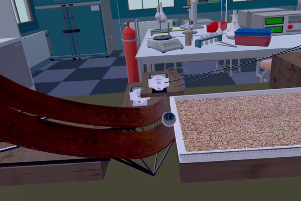
A rolling object carries its energy in two places at once, and that single fact sets almost every number in this laboratory. Gravity roller conveyors in warehouses, ball bearings, bobsled and skateboard tracks and the gravity-fed marble runs used to teach mechanics all depend on knowing how fast a rolling body will be travelling at the foot of a slope — and a rolling body never arrives as fast as a sliding one released from the same height.
When a body slides without friction, every joule of gravitational potential energy it gives up becomes translational kinetic energy. When it rolls without slipping, that same energy has to be shared with rotation, because the contact surface exerts the friction torque that spins the body up. For a solid sphere the rotational share is a fixed two sevenths of the total, leaving only five sevenths to drive the sphere forward. This is the origin of the factor 10/7 that runs through the whole laboratory: it replaces the familiar v = √(2gh) of the sliding case with v = √(10gh/7), about 15 % slower. Because gravity is a conservative force, the shape and the length of the slope are irrelevant to that speed — only the vertical drop matters.
In this laboratory you compare two ramps whose descending sections are both 1.0 m long but which fall at different angles, 15° for ramp 1 and 20° for ramp 2, and therefore through different heights. You will predict the speed of the marble at the foot of each descent from energy conservation alone, then measure it with a pair of photodiode gates and an electronic timer. You will then predict how high the marble rises after it leaves the short 45° ascending section at the end of each ramp, measure that as well, and decide which of the two geometries launches the marble higher — and why the measured values fall a little short of the predicted ones.
Educational Goals
Rolling motion and the sharing of energy
- Explain why a rolling sphere reaches the foot of a slope more slowly than a sliding block released from the same height, and say where the missing translational kinetic energy has gone.
- Trace the factors 10/7 and 5/7 back to the moment of inertia of a solid sphere, I = (2/5)mr2, and the rolling condition v = ωr.
Prediction from conservation of mechanical energy
- Use mgh = ½mv2 + ½Iω2 to predict the speed of the marble at the foot of a slope from the drop height alone, before any measurement is taken.
- Recognise that the prediction depends only on the vertical drop, so that ramp length, curvature and angle enter only through h = Δx · sin θ.
Kinematics of the launch and the flight
- Compute the deceleration of a rolling sphere on an upward slope and apply va2 = vd2 + 2aΔx to find the speed at which the marble leaves the ramp.
- Resolve that speed into components and find the apex height of the subsequent free flight.
The influence of ramp geometry
- Predict and then confirm that the steeper descent produces the greater launch speed and the greater apex height, and quantify by how much.
- Explain why the two ascending sections, being identical, make the initial speed the only variable that decides the final height.
Measurement with photodiode gates and an electronic timer
- Place the two gates correctly, trigger a run with button A or button B, and read the value the timer returns.
- Describe what the instrument actually measures and what has to be known about the apparatus before that reading can be turned into a speed.
Comparison of model with measurement
- Quantify the difference between predicted and measured values and account for it in terms of rolling resistance and air resistance.
Protocol
Introduction
- We want to estimate the speed at the bottom of the descending slope of each ramp in order to estimate which ramp will give the marble the highest takeoff.
- Two different ramps are used for this laboratory :
- Ramp 1 is 0.259 m high and has an inclination angle of 15°
- Ramp 2 is 0.342 m high and has an inclination angle of 20°
- Each of the two ramps can be broken down into two portions : a descending portion, and an ascending portion.
- The two ramps differ with respect to the angle and the height of their descending portion. The length of the descending portion of both ramps is 1 m.
- The ascending portion of each ramp is otherwise identical.
Manipulations A
Considering the parameters provided above and knowing that the acceleration due to gravity is 9.8 m/s, estimate the speed at the bottom of each descending ramp (in m/s).
- Position one of the stopwatch sensors on the small board placed at the end of the descending slope of the ramps (white location). Position the 2nd sensor on the other small board placed at the end of the ramps (black location).
- Position the marble at the top of ramp 1 on the gray horizontal line.
- Press button A in order to obtain the speed of the marble at the end of the descending slope of ramp 1.
- Observe the demonstration.
- The demonstration data are entered in the results table. Consult the data obtained in order to compare them to your calculations.
- Repeat steps 2 to 5 using ramp 2.
Question A
Knowing the speed at the bottom of each descending ramp, considering the following parameters :
- Length of ascending ramps: 0.17 m
- Angle of ascending ramps: 45°
What will be the maximum height reached by each marble (in m)?
Manipulations B
- Position the marble at the top of ramp 1 on the gray horizontal line.
- Press button B in order to obtain the maximum height reached by the marble after taking off from ramp 1.
- Observe the demonstration.
- The demonstration data are entered in the results table. Consult the data obtained in order to compare them to your calculations.
- Repeat steps 1 to 4 using ramp 2.
Questions B
- Which ramp will give the marble its maximum height?
- If the calculations are different from the experimental data, what factors explain these differences?
Anticipated Outcomes
The apparatus supplies these parameters, and every figure below follows from them:
- Descending length of both ramps Δxd = 1.0 m
- Descending angle of ramp 1, θd1 = 15°, so ramp 1 falls 1.0 × sin 15° = 0.259 m
- Descending angle of ramp 2, θd2 = 20°, so ramp 2 falls 1.0 × sin 20° = 0.342 m
- Ascending length of both ramps Δxa = 0.17 m at θa = 45°, so the lip of each ramp sits h0 = 0.17 × sin 45° = 0.12 m above the table
- Acceleration due to gravity g = 9.8 m/s2
Step 1 — speed at the foot of each descent. A marble that rolls without slipping stores kinetic energy in two forms at once, and both have to be paid for out of the potential energy it gives up:
mgh = ½mv2 + ½Iω2, with I = (2/5)mr2 and ω = v/r
Substituting the moment of inertia and the rolling condition collapses the rotational term into (1/5)mv2, so mgh = ½mv2 + (1/5)mv2 = (7/10)mv2. The mass cancels, and rearranging gives the working equation for a rolling sphere on any slope:
v = √(10 g Δx sin θ / 7)
Showing the substitution once, for ramp 1:
vd1 = √((10 × 9.8 × 1.0 × sin 15°) / 7) = √((10 × 9.8 × 0.259) / 7) = √3.62 = 1.91 m/s
and for ramp 2, whose drop is 0.342 m:
vd2 = √((10 × 9.8 × 0.342) / 7) = √4.79 = 2.19 m/s
Step 2 — deceleration on the ascending section. The same analysis run uphill gives the acceleration of a rolling sphere on a slope. It is a constant, it does not depend on the mass or the radius of the marble, and it is five sevenths of what a frictionless sliding block would experience:
a = −(5/7) g sin θa = −(5 × 9.8 × sin 45°) / 7 = −4.95 m/s2
The minus sign says the acceleration opposes the motion; the sin θ factor is the component of gravity along the slope; the 5/7 is again the penalty for having to slow the spin as well as the translation.
Step 3 — speed at the lip of the ramp. With a constant acceleration over a known distance, the third kinematic equation gives the speed at which the marble leaves the ramp:
va = √(vd2 + 2 a Δxa)
va1 = √(3.62 + 2 × (−4.95) × 0.17) = √(3.62 − 1.68) = √1.94 = 1.40 m/s
va2 = √(4.79 − 1.68) = √3.11 = 1.76 m/s
Step 4 — the vertical component at launch. Only the vertical part of that velocity can be traded for height; the horizontal part carries the marble out over the landing tray and is still there at the apex. At a launch angle of 45°:
vay = va × sin 45° → va1y = 1.40 × 0.707 = 0.99 m/s and va2y = 1.76 × 0.707 = 1.25 m/s
Step 5 — the apex height. Once the marble is airborne no torque acts on it, so it keeps spinning at whatever rate it had at the lip and its rotational energy is simply carried along, taking no part in the climb. Applying the third kinematic equation to the vertical direction alone, with v = 0 at the apex and a = −g, and measuring from the table rather than from the lip:
h = h0 + vay2 / (2g)
h1 = 0.12 + 0.992 / (2 × 9.8) = 0.12 + 0.05 = 0.17 m
h2 = 0.12 + 1.252 / (2 × 9.8) = 0.12 + 0.08 = 0.20 m
| Quantity | Ramp 1 | Ramp 2 |
|---|---|---|
| Descending length | 1.0 m | 1.0 m |
| Descending angle | 15° | 20° |
| Vertical drop of the descent | 0.259 m | 0.342 m |
| Ascending length | 0.17 m | 0.17 m |
| Ascending angle | 45° | 45° |
| Speed at the foot of the descent | 1.91 m/s | 2.19 m/s |
| Speed at the lip of the ascent | 1.40 m/s | 1.76 m/s |
| Vertical speed at the lip | 0.99 m/s | 1.25 m/s |
| Apex height above the table | 0.17 m | 0.20 m |
Why the result comes out this way. Both descending sections are the same length, so the only thing that distinguishes them is the angle, and the angle acts on the marble entirely through the vertical drop Δx sin θ. Ramp 2 falls 0.342 m against ramp 1’s 0.259 m, a third further, and since v varies as the square root of the drop, that third becomes only a 15 % gain in speed — a useful reminder that speed is a much less sensitive function of height than students expect. That 15 % is then carried through the ascent, where both ramps take the same fixed toll of 1.68 m2/s2 out of v2, and because the toll is subtracted from a smaller number on ramp 1 it costs ramp 1 proportionally more: ramp 1 loses 27 % of its speed climbing the lip, ramp 2 only 20 %. Ramp 2 therefore arrives at the lip 26 % faster than ramp 1, a bigger margin than it had at the bottom. In the apex height that advantage is compressed again, because the 0.12 m of the lip itself is common to both and only the flight adds to it: 0.05 m against 0.08 m. Ramp 2 gives the marble the greater maximum height, and the answer to question B is that a steeper descent wins, but by markedly less than the difference in the angles would suggest.
The two routes agree exactly. Steps 2 and 3 use a kinematic argument, but the same answer follows from energy alone: (7/10)va2 = (7/10)vd2 − gΔh with Δh = 0.17 × sin 45° = 0.12 m gives va2 = vd2 − 1.68, which is precisely what the kinematic route returns. This is worth pointing out to students, because it shows that the constant-acceleration step is a convenience rather than an extra assumption, and that the calculation would survive unchanged if the ramps were curved instead of straight, so long as the marble keeps rolling and the drop and rise heights are unchanged.
Summary of Assignment by Grade Range
Grade 9–10
Focus: observation, vocabulary and the qualitative link between height, speed and distance travelled. Students release the marble on each ramp, watch what happens, and put into words that the steeper ramp makes the marble faster at the bottom and sends it higher after the lip. The words potential energy, kinetic energy, rolling and sliding are introduced and used, without the equations.
Activities: predict which ramp will win before running either one and record the prediction; describe the difference between the two runs in a short paragraph; mark where the marble lands in the tray for each ramp and compare; state which measurements would have to be taken to turn the description into a number. Any calculation at this level is done with teacher support.
Grade 11
Focus: quantitative treatment. Students carry out the full calculation of the two speeds and the two apex heights themselves, using conservation of mechanical energy and the third kinematic equation, and compare each predicted value with the measured one.
Activities: compute vd for both ramps from the drop heights; compute the deceleration on the ascending section and hence va and vay; obtain both apex heights; tabulate predicted against measured and express the difference as a percentage; explain the direction of that difference in terms of friction and air resistance rather than merely noting it. Students should be able to say why the 32 % difference in drop height produces only a 15 % difference in speed.
Grade 12 / College Level
Focus: derivation, model validation and error analysis. The 10/7 and 5/7 factors are derived rather than quoted, and the assumptions behind them are made explicit and tested.
Activities: derive v = √(10gh/7) from mgh = ½mv2 + ½Iω2 for a solid sphere and repeat the derivation for a hollow sphere (I = (2/3)mr2, factor 6/5) and a cylinder, then predict how the results would change; show that the energy and kinematic routes to va are algebraically identical and explain why the ramp’s curvature therefore does not matter; identify systematic and random error sources separately and estimate the size of each; state what the retained rotational energy at the lip does to the flight and quantify the error made by ignoring it; assess whether a single run per ramp can support the conclusion drawn, and design the repetition schedule that would.
Laboratory essentials
Instruments
- Ramp 1 — descending section 1.0 m long at 15° (falls 0.259 m), ascending section 0.17 m at 45°
- Ramp 2 — descending section 1.0 m long at 20° (falls 0.342 m), ascending section 0.17 m at 45°
- Marble (solid sphere)
- Two photodiode gates on stands, one at the foot of the descent and one at the end of the ramp
- Electronic timer with digital display, wired to the gates
- Button A (speed at the foot of the descent) and button B (maximum height after launch)
- Sand-filled landing tray with a graduated edge
- Ruler
Products
- None — this laboratory uses no chemical products.