

A solenoid is a coil of wire that becomes a magnet when current flows through it, and stops being one the instant the current stops. That single property — a magnet with a switch — is what makes electromagnetism useful. It is how a scrapyard crane picks up a car and drops it, how the starter of an engine throws its pinion forward, how a door lock releases when a card is presented, how a loudspeaker cone is driven, how a relay lets a small current control a large one, and, wound from superconducting wire and cooled with liquid helium, how the several-tesla field of a magnetic resonance scanner is produced.
The field inside a long coil is uniform and points along the axis, and its strength is B = µ0 nI, where n is the number of turns per metre and I the current. Three things can therefore be changed to make the coil stronger: more turns in the same length, more current, or a core that is itself magnetisable. The third is the largest lever of the three. A ferromagnetic core placed inside the coil is magnetised by the coil’s own field and adds its own contribution to it, which is why an iron-cored electromagnet can be hundreds of times stronger than the same coil wound around nothing at all.
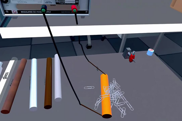
In this laboratory you will test each of the three factors in turn while holding the other two fixed. Part A pushes seven different cores — soft iron, nickel, glass, wood, aluminium, copper and no core at all — into a 600-turn coil at a fixed 15 V. Part B keeps the soft iron core and steps the supply from 30 V to 15 V to 7 V. Part C keeps the core and the voltage and changes the coil, from 15 turns to 300 to 600. The strength of the magnet is judged each time by the same crude but effective gauge: the percentage of the paper clips on the bench that it will lift.
Educational Goals
Understanding what makes an electromagnet
- State the three variables that set a solenoid’s field strength — turns per unit length, current, and the permeability of the core — and write B = µ0µrnI.
- Explain why a solenoid can be switched off and a permanent magnet cannot, and name three devices that depend on that difference.
Controlling variables
- Change one factor at a time and keep the other two fixed, and identify which quantity is the controlled one in each of the three parts.
- Recognise that the three parts share a common configuration — 600 turns, soft iron, 15 V — and use it to check that the three tables agree with one another.
Distinguishing magnetic materials
- Sort the seven cores into ferromagnetic and non-magnetic, and explain the result in terms of relative permeability rather than by listing which ones worked.
- Explain why copper and aluminium, both excellent electrical conductors, are useless as magnetic cores.
Using an indirect measurement
- Explain why the percentage of clips lifted is a threshold indicator and not a proportional measure of field strength.
- Give reasons why a measurement of this kind must be repeated before any two configurations can be ranked.
Handling the apparatus
- Set a bench supply to a stated potential difference, connect a coil to it, and shut it down safely between trials.
- Keep the number of clips available roughly constant between trials, and say why the result would otherwise not be comparable.
Protocol
Part A : The nature of the core
- Connect the 600-turn solenoid to the power source using the connectors.
- Have more than 35 paper clips on the counter. Make sure to add paper clips between each experiment if some have fallen off the table.
- Place the soft iron core into the solenoid.
- Turn on the power source.
- Adjust the potential difference to 15 V.
- Touch the paper clips with the solenoid.
- Gently move the solenoid away from the paper clips and then remove the core.
- The approximate percentage of paper clips that are attracted by the solenoid is found in the results table.
- Repeat steps 1 to 8 with the five other types of cores and without a core (air core).
Part B : The current intensity
- Place the soft iron core into the solenoid.
- Adjust the potential difference of the source to 30 V.
- Touch the paperclips with the solenoid.
- Gently move the solenoid away from the paperclips and then remove the core.
- The approximate percentage of paper clips that are attracted by the solenoid is found in the results table.
- Decrease the potential to 15v. Place the soft iron core in the solenoid and touch the paper clips with the solenoid. Note the approximate percentage of paper clips that are attracted by the solenoid in the results table.
- Remove the core from the solenoid.
- Decrease the potential to 7v. Place the soft iron core into the solenoid and touch the paper clips with the solenoid. Note the approximate percentage of paper clips that are attracted by the solenoid in the results table. Remove the core from the solenoid.
- Disconnect the 600-turn solenoid from the current source, reattach the connectors to the terminals and place it on the table.
Part C : The density of turns
- Connect the 15-turn solenoid to the power source.
- Place the soft iron core into the solenoid.
- Adjust the potential difference to 15 V.
- Touch the paperclips with the solenoid.
- Gently move the solenoid away from the paperclips and then remove the core.
- The approximate percentage of paper clips that are attracted by the solenoid is found in the results table.
- Disconnect the 15-turn solenoid from the current source, reattach the connectors to the terminals and store it on the table.
- Repeat steps 1 to 7 with the 300-turn solenoid.
Anticipated Outcomes
| Nature of the core | Magnetic classification | Approximate percentage of paper clips attracted |
|---|---|---|
| Soft iron | ferromagnetic, relative permeability in the thousands | 40 % |
| Nickel | ferromagnetic, permeability in the hundreds, saturating at about a third of iron’s magnetisation | 10 % |
| Glass | non-magnetic, µr = 1 to within a few parts per million | 0 % |
| Wood | non-magnetic | 0 % |
| Aluminium | paramagnetic, µr = 1.000 022 | 0 % |
| Copper | diamagnetic, µr = 0.999 994 | 0 % |
| Air (no core) | µr = 1.000 000 4 | 0 % |
| Potential difference (V) | Approximate percentage of paper clips attracted |
|---|---|
| 30 | 100 % |
| 15 | 40 % |
| 7 | 20 % |
| Number of turns | Approximate percentage of paper clips attracted |
|---|---|
| 15 | 2 % |
| 300 | 20 % |
| 600 | 40 % |
Reading these results. Each figure is the percentage of the paper clips on the bench that the solenoid lifts, not a count, so it does not depend on how many clips happen to be laid out. The field inside a solenoid is proportional to the number of turns per unit length and to the current through it, B = µ0µrnI, but the fraction of clips lifted is not proportional to B. The force on a clip depends on the square of the field and on how sharply the field falls away from the pole, and a clip only rises once that force exceeds its weight. The percentages therefore climb steeply once the field passes the threshold for the bulk of the clips, which is why 30 V lifts essentially all of them and why the step from 7 V to 15 V doubles the tally for a doubling of the field while the step from 15 V to 30 V does considerably more than that.
Why the core matters more than anything else. Inserting a ferromagnetic core does not merely help the coil’s field along; it supplies most of the field. The atomic magnetic moments in iron are already aligned within microscopic domains, and the coil’s field does no more than swing whole domains into line with it — a large effect obtained for a small cause. Nickel is ferromagnetic too, which is why it is the only other core that lifts anything, but its saturation magnetisation is about 0.6 T against iron’s 2.15 T and its permeability is far lower, so it manages a quarter of iron’s result. Everything else on the list has a relative permeability indistinguishable from one at the precision of this experiment: aluminium is very weakly attracted to a field and copper very weakly repelled, both by a few parts per million, and neither effect could lift a paper clip under any circumstances. Note that copper and aluminium are excellent electrical conductors and completely useless as magnetic cores — conducting electricity and conducting magnetic flux are unrelated properties, and students routinely expect otherwise.
Why a short iron rod does not give the thousandfold gain its permeability promises. Bulk soft iron has a relative permeability of several thousand, yet the cored coil here is nothing like a thousand times stronger than the empty one. The reason is geometry. As soon as the rod is magnetised, free poles appear at its two ends and these produce a field inside the rod that opposes the magnetisation — the demagnetising field. Its size depends on the shape: long and thin is good, short and fat is bad, and for a rod ten times as long as it is wide the effective permeability is limited to a few tens whatever the material’s intrinsic value. This is precisely why transformers and motors use closed magnetic circuits with no air gap, and why the horseshoe shape was invented.
A subtlety in Part C worth raising with an able class. The usual statement is that the field is proportional to the number of turns, and at constant current it is. But this protocol holds the voltage constant, and turns and resistance are not independent: winding more turns of the same wire on the same former lengthens the wire in proportion, so R rises with N, the current V/R falls in proportion, and the two effects cancel exactly — B = µ0(N/L)(V/R) with R ∝ N leaves no N at all. On that reasoning the three coils at 15 V should perform identically, and they plainly do not. The resolution is that the three coils are not the same wire on the same former: a 15-turn coil is normally wound in much heavier wire, so its resistance is far lower than a simple proportionality would suggest, and the coils differ in length as well. The honest summary is that Part C compares three particular coils rather than isolating the number of turns, and a class that wants the clean experiment should measure the resistance of each coil first and either work at constant current or correct for it.
Expect scatter, and repeat. Which clips are touched and lifted varies from one trial to the next, so a single measurement can land roughly 15 percentage points either side of the values above. On an unlucky pair of trials a weaker configuration can appear to out-perform a stronger one. That is ordinary sampling behaviour, not a fault in the apparatus, and the remedy is the ordinary one: repeat each measurement several times and compare the averages rather than single readings. Recognising that one trial is not evidence of a trend is part of the exercise. It also matters that the clips are re-laid between trials and that their number is kept roughly constant, since a bench with ten clips left on it and a bench with forty do not present the same target.
Honest limits of this experiment. No field is ever measured. The percentage of clips lifted is a threshold indicator: it responds to the field, but through the clips’ mass, their shape, how they are heaped and where the pole touches them, so it cannot be converted into teslas and the three tables cannot be plotted against one another on any common scale. The current is never displayed either, only the voltage, so B = µ0µrnI has to be applied through Ohm’s law with a coil resistance that is not given. Nor does the experiment show hysteresis, although it is present in every iron core: a rod that has been magnetised keeps some magnetisation when the current stops, which is why the protocol has you remove the core before the next trial. A class with a Hall probe or a compass-and-stopwatch method can turn all three parts into genuine measurements; without one, this laboratory establishes an ordering and a set of thresholds, which is a legitimate result provided it is not written up as though teslas had been measured.
Summary of Assignment by Grade Range
Grade 9–10
Focus. What an electromagnet is and what makes it stronger.
Activities. Carry out all three parts and fill in the three tables. Before each trial, predict whether the result will be higher or lower than the one before it, and afterwards count how many predictions were right.
Expected of the student. Name the three factors that change a solenoid’s strength; sort the seven cores into those that work and those that do not and say what the working ones have in common; state that the coil is a magnet only while current flows; and give two everyday uses of an electromagnet.
Grade 11
Focus. Controlled variables and the relationship behind the tables.
Activities. Identify what is held fixed in each part and check that the three tables agree at the configuration they share. Use B = µ0µrnI with Ohm’s law to predict the ratio of the fields at 30, 15 and 7 V, and compare that ratio with the percentages actually obtained. Repeat one configuration several times and quote a mean with a spread.
Expected of the student. Explain why the percentages rise faster than the field does; explain why the current is proportional to the dial setting; account for nickel’s weaker result in terms of permeability and saturation; and state why aluminium and copper fail despite being good conductors.
Grade 12 / College Level
Focus. Magnetic materials, and the difference between an ordering and a measurement.
Activities. Analyse the force on a clip as depending on the gradient of B2 and explain the threshold behaviour of the percentages. Examine the constant-voltage design of Part C and determine what would have to be known about the three coils for the number of turns to be isolated. Estimate the effect of the demagnetising field on a short rod and explain why closed magnetic circuits are used in transformers.
Expected of the student. Distinguish ferromagnetism from paramagnetism and diamagnetism by mechanism and by order of magnitude; explain hysteresis and why the core is removed between trials; design a version of this experiment that would yield a field in teslas; and state clearly which conclusions on this page are supported by the data and which are brought in from theory.
Laboratory essentials
Instruments
- Solenoid, 15 turns
- Solenoid, 300 turns
- Solenoid, 600 turns
- Variable DC power source (7 to 30 V)
- Connecting wires (2)
- Cores (6): soft iron, nickel, glass, wood, aluminium, copper
- Box of small paper clips, at least 35 laid out on the bench