Educational Goals
Understanding Pulley Systems and Mechanical Advantage
- Explore how a 5-strand pulley reduces the input force needed to lift heavy loads, using a real-world theater stage design as a case study.
- Apply Newton’s laws to analyze forces and accelerations in a dynamic system.
Energy Transformations and Efficiency
- Calculate work done by gravitational and frictional forces during motion on an inclined plane.
- Investigate energy conservation principles in systems with non-conservative forces (e.g., friction).
Experimental Design and Critical Analysis
- Use free-body diagrams (FBDs) to model forces acting on a moving gondola and pulley system.
- Quantify the relationship between displacement, acceleration, and time using kinematic equations.
Real-World Applications
- Relate pulley mechanics to engineering challenges in theater stage design, such as lifting actors safely and efficiently.
Protocol
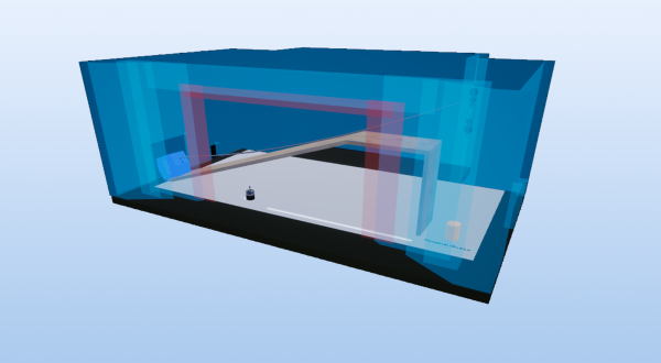
- A stage model reproduces a lifting mechanism allowing the vertical movement of an actor (total mass: m=150kg) from one floor to another via a gondola moving on an inclined ramp (θ=18∘; L=12m). The movement is generated by a suspended accelerating counterweight attached to a five-strand hoist. The critical parameters include: Friction force: Ff=0.24×N; where N is the normal force; and Time constraint: Δt=8s to cover Δx=12 m.
- With the simulation; you must explain the operation of the hoist and determine the conditions under which it should be used to achieve the desired movement.
- Proceed to suspend a mass mc on the mobile assembly of the hoist; respecting the configuration with five load-bearing strands.
- Press the button to start the demonstration.
- Observe the demonstration. Measure: Travel time (Δt); and Displacement of the gondola (Δx) and of the counterweight (Δy=Δx/5).
- Explain how a five-rope pulley system allows for lifting a heavy load at a constant speed to a height h.
- Explain how the use of the pulley will make things easier.
- Determine the acceleration of the gondola as well as that of the weight suspended from the hoist.
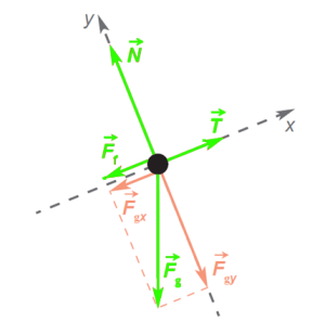
- Draw the force diagram of the gondola when it is moving on the ramp. Name each of the force vectors that you represent on this force diagram; then indicate the appropriate symbol and; if possible; how one can calculate its magnitude.
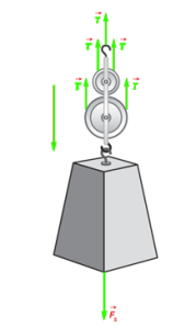
- Draw the force diagram of the movable part of the pulley system (the suspended weight and the two movable pulleys). Name each of the force vectors on this force diagram; then indicate the appropriate symbol and; if possible; how its magnitude can be calculated.
- Determine the parameters that must be specified to the prop masters so they can use the hoist in such a way that the movement of the gondola meets the director’s requirements (length and duration of the movement).
- Determine the numerical value of the parameters that the prop masters will need to control so that the fall of the weight suspended from the gondola produces the desired movement.
Anticipated Outcomes
The use of a five-strand load-bearing hoist induces a theoretical mechanical advantage of MA=5, reducing the driving force (Fmot) required to lift a load according to the relationship: Fmot=Pload/MA=mg/5, where Pload is the weight of the load. This effect results from the balanced distribution of tension (T) on the five load-bearing strands and the movable pulleys. However, in accordance with the principle of conservation of energy, the displacement of the string (Δx string) is proportional to the number of strands: Δxchord=MA×Δh=5h, where Δh is the lifting height. Thus, to raise the load by h, each strand shortens by h, requiring equivalent mechanical work on the rope. Since the basket must travel a distance of 12.0 m, the rope must also move 12.0 m. However, with a single pulley, the suspended weight would have to be able to fall by 12.0 m, which is not possible given the dimensions of the stage. With a five-strand load-bearing hoist, the weight moves five times less than the rope (i.e. five times less than the basket). The load can therefore be lowered five times smaller than the length of the ramp, i.e. 2.40 m (12.0 m / 5).
The forces acting on the moving part of the hoist will be the same (five upward tension vectors and one downward weight vector). In addition, the ratio between the displacement of the rope (and therefore of the basket) and that of the suspended weight will still be equal to five since this is the number of load-bearing strands that this hoist has.
Acceleration of the nacelle According to the scenario, the basket is initially at rest (vi = 0), its displacement Δx is 12.0 m and the duration of the movement Δt is 8.00 s. We can therefore calculate the acceleration of the basket using the following relationship: Δx = viΔt +( aΔt2)/2 12.0 m = 0 m/s • 8.00 s + a(8.00 s)2/2 at ≈ 0.375 m/s2
Acceleration of the weight suspended from the hoist We know that the weight is initially at rest (vi = 0), that it falls by 2.40 m (Δx) and that the duration of the movement Δt is 8.00 s. We can therefore calculate the acceleration of this weight using the following relation: Δx = viΔt + aΔt)2/2 2.40 m = 0 m/s • 8.00 s + a(8.00 s)2/2 at ≈ 0.0750 m/s)2
Force diagram of the gondola when it is moving on the ramp T : Tension in the rope: an unknown whose value will have to be determined. Fgx : Component of the force of gravity in the direction of motion. It can be calculated using the following relationship: Fgx = mg sin θ Fgx = 150 kg × 9.80 N/kg × sin 18.0° FGX ≈ 454 N Fgy : Component of the force of gravity in the direction perpendicular to motion. It can be calculated using the following relationship: Fgy = mg cos θ Fgy = 150 kg × 9.80 N/kg × cos 18.0° Fgy ≈ 1398 N (1.40 × 10³ N) N : Normal strength. According to the FBD, N and Fgy are in equilibrium since there is no motion in the perpendicular direction of the plane. N = Fgy ≈ 1398 N (1.40 × 10³ N) Ff : Frictional force. Based on the scenario, this force is equivalent to 24% of the normal force N. Ff = 0.24 × (1.40 × 103 N) ff ≈ 336 N
Force diagram of the movable part of the pulley system T : Tension in the rope: an unknown whose value will have to be determined. However, since it is the same chord as the basket, the value of T will be the same in both analyses. Fg: Force of gravity. It can be calculated using the following relationship: Fg = mg, where m is an unknown whose value will have to be determined.
Numerical value of the parameters Prop makers must know the height h of fall that will allow the basket to be pulled along the entire length of the ramp (12.0 m). They must also know the mass m of the weight to be suspended from the hoist. If it is too small, it will not be enough to lift the basket; If it is too large, it will cause a higher acceleration than necessary.
Height h of fall of the weight suspended from the hoist The hoist has five load-bearing strands. The weight suspended from the hoist will therefore fall five times shorter than the displacement of the basket (12.0 m) since each strand will lengthen of the same length. Prop makers will therefore have to make sure that the weight drops 2.40 m high. h = 12.0 m ÷ 5 = 2.40 m
Mass m to be suspended from the hoist
- From the FBD of the basket, the amount of the tension in the rope can be deduced. It is sufficient to apply Newton’s second law to the forces which are exerted parallel to the ramp.
F = ma T – Fgx – Ff = 150 kg × 0.375 m/s2 T – 454 N – 336 N = 56.25 N T ≈ 846 N
- The magnitude of the mass to be suspended from the FBD of the moving part of the hoist can be deduced. It is sufficient to apply Newton’s second law to the forces exerted on the moving part of the hoist.
F = ma Fg – 5T = m(0.0750 m/s2) m(9.80 m/s2) – 5 × 846 N = (0.0750 m/s2)m 4230 N = (9.80m/s2)m – (0.0750 m/s2)m m ≈ 435 kg Since the mass of the pulleys is considered negligible, the value obtained represents the mass of the weight to be suspended from the hoist.
Summary of Assignment by Grade Range
Grades 6–8
Focus:
- Introduction to simple machines and forces.
Tasks:
- Build a miniature ramp and pulley system.
- Measure how counterweight mass affects gondola speed.
Outcomes:
- Recognize pulleys as force multipliers.
- Identify energy losses as “heat from friction.”
Grades 9–10
Focus:
- Quantitative analysis of forces and motion.
Tasks:
- Calculate gondola acceleration using Δx=0.5*a*t²
- Draw FBDs for the gondola and pulley.
Outcomes:
- Apply Newton’s second law to real systems.
- Explain why efficiency is <100%.
Grades 11–12
Focus:
- Advanced optimization and error analysis.
Tasks:
- Derive the counterweight mass using torque equations.
- Propose design changes to improve efficiency (e.g., lubricated rails).
Outcomes:
- Write lab reports with error propagation analysis.
- Model energy losses using computational tools.
This experiment mirrors challenges faced by theater engineers, who must balance safety, precision, and aesthetics. The pulley system demonstrates how mechanical advantage simplifies lifting heavy loads but also highlights trade-offs like energy dissipation due to friction—a critical consideration in stage design.
Laboratory essentials
Instruments
- Miniature scene
- 2x Wood boards
- Weight
- Miniature 5 strand load-bearing hoist